Instead of configuring each appliance separately, you can create various Deployment Profiles and provision a device by applying the profile you want. For example, you can create a standard format for your branch.
Tip  For smoother workflow, complete the Configuration > DHCP Server tab before creating Deployment Profiles.
You can use Deployment Profiles to simplify provisioning, whether or not you choose to create and use Business Intent Overlays.
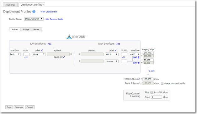 |
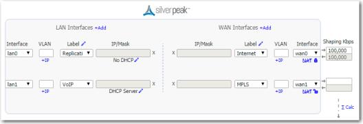
Note  IP/Mask fields are not editable because they are appliance-specific.
|
n
|
|
n
|
|
•
|
|
•
|
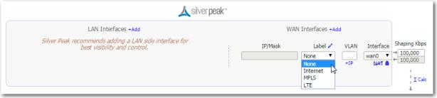
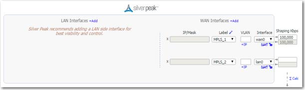
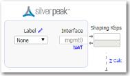
Select Configuration > Interface Labels.
|
|
n
|
|
n
|
The global defaults are set in Configuration > DHCP Server and pre-populate this page. The other choices are No DHCP and having the appliance act as a DHCP Relay.
|
|
n
|
To customize an individual interface in the Deployment Profile, click the Edit icon under the IP/Mask field, to the right of the displayed DHCP label.
|
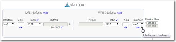
WAN interface hardening: In Router mode and in Bridge mode, you can provide security on any WAN-side interface by hardening the interface. This means:
|
•
|
For traffic inbound from the WAN, the appliance accepts only IPSec tunnel packets.
|
|
•
|
For traffic outbound to the WAN, the appliance only allows IPSec tunnel packets and management traffic.
|
|
•
|
Click the lock icon to toggle between hardening and unhardening an interface.
|
NAT: If the appliance is behind a NAT-ed interface, select NAT (without the strikethrough). When using NAT, use in-line Router mode to ensure that addressing works properly. That means you configure paired single or dual WAN and LAN interfaces on the appliance.
Shaping: You can limit bandwidth selectively on each WAN interface.
|
•
|
Total Outbound bandwidth is licensed by model. It's the same as max system bandwidth.
|
|
•
|
To enter values for shaping inbound traffic, which is optional, you must first select Shape Inbound Traffic.
|
EdgeConnect Licensing: Only visible on EC appliances
|
•
|
By default, every EC has a max system bandwidth of 200 Mbps. For more bandwidth, you can purchase Plus, and then select it here for this profile.
|
|
•
|
If you've purchased a reserve of Boost for your network, you can allocate a portion of it in a Deployment Profile. You can also direct allocations to specific types of traffic in the Business Intent Overlays.
|
|
•
|
|
n
|
DHCP Pool Subnet/Mask is the full range of IP addresses that you make available for your network.
|
|
n
|
Subnet Mask is a mask that specifies the default number of IP addresses reserved for any subnet. For example, entering 24 reserves 256 IP addresses.
|
|
n
|
Start Offset specifies how many addresses not to allocate at the beginning of the subnet's range. For example, entering 10 means that the first ten IP addresses in the subnet aren't available.
|
|
n
|
End Offset specifies how many IP addresses are not available at the end of the subnet's range.
|
|
n
|
Default lease and Maximum lease specify, in hours, how long an interface can keep a DHCP–assigned IP address.
|
|
n
|
Default gateway, when selected, indicates that
|
|
n
|
DNS server(s) specifies the associated Domain Name System server(s).
|
|
n
|
NTP server(s) specifies the associated Network Time Protocol server(s).
|
|
n
|
NetBIOS name server(s) is used for Windows (SMB) type sharing and messaging. It resolves the names when you are mapping a drive or connecting to a printer.
|
|
n
|
The NetBIOS node type of a networked computer relates to how it resolves NetBIOS names to IP addresses. There are four node types:
|
|
•
|
B-node = 0x01 Broadcast
|
|
•
|
P-node = 0x02 Peer (WINS only)
|
|
•
|
M-node = 0x04 Mixed (broadcast, then WINS)
|
|
•
|
H-node = 0x08 Hybrid (WINS, then broadcast)
|
|
n
|
Destination DHCP Server is the IP address of the DHCP server assigning the IP addresses.
|
|
n
|
Enable Option 82, when selected, inserts additional information into the packet header to identify the client's point of attachment.
|
|
n
|
Option 82 Policy tells the relay what to do with the hex string it receives. The choices are append, replace, forward, or discard.
|
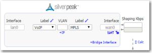
In Bridge Mode and in Router Mode, you can provide security on any WAN-side interface by hardening the interface. This means:
|
•
|
For traffic inbound from the WAN, the appliance accepts only IPSec tunnel packets.
|
|
•
|
For traffic outbound to the WAN, the appliance only allows IPSec tunnel packets and management traffic.
|
|
•
|
Click the lock icon to toggle between hardening and unhardening an interface.
|
 |
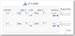 |
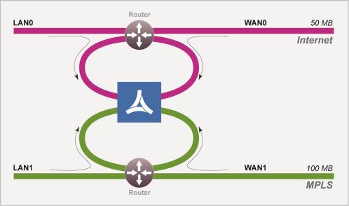
For best performance, visibility, and control, Silver Peak recommends Options #1 and #2, which use separate LAN and WAN interfaces. And when using NAT, use Options #1 or #2 to ensure that addressing works properly.
 |
|
a
|
You can put Silver Peak in-path. In this case, if there is a failure, you need other redundant paths for high availability.
|
|
b
|
You can put Silver Peak out-of-path. You can redirect LAN-side traffic and WAN-side traffic from a router or L3 switch to the corresponding Silverpeak interface, using WCCP or PBR (Policy-Based Routing).
|
 |
 |
|
a
|
You can put Silver Peak in-path. In this case, if there is a failure, you need other redundant paths for high availability.
|
|
b
|
You can put Silver Peak out-of-path. You can redirect LAN-side traffic and WAN-side traffic from a router or L3 switch to the corresponding Silverpeak interface, using WCCP or PBR (Policy-Based Routing).
|
 |
|
•
|
This mode only supports out-of-path.
|
|
•
|
For better performance, control, and visibility, Silver Peak recommends Router mode Option #1 instead of this option.
|
 |
This is also known as Dual-Homed Router Mode.
|
•
|
This mode only supports out-of-path.
|
|
•
|
For better performance, control, and visibility, Silver Peak recommends Router mode Option #2 instead of this option.
|
|
•
|
PBR (Policy-Based Routing) — configured on the router. No other special configuration required on the appliance. This is also known as FBR (Filter-Based Forwarding).
|
|
•
|
WCCP (Web Cache Communication Protocol) — configured on both the router and the Silver Peak appliance. You can also use WCCP for redundancy and load balancing.
|
|
•
|
Host routing — the server/end station has a default or subnet-based static route that points to the Silver Peak appliance as its next hop. Host routing is the preferred method when a virtual appliance is using a single interface, mgmt0, for datapath traffic (also known as Server Mode).
|
|
•
|
If you use subnet sharing (which relies on advertising local subnets between Silver Peak appliances) or route policies (which specify destination IP addresses), then you only need LAN-side redirection.
|
|
•
|
If, instead, you rely on TCP-based or IP-based auto-optimization (which relies on initial handshaking outside a tunnel), then you must also set up inbound and outbound redirection on the WAN router.
|
|
•
|
If you enable auto-tunnel, then the initial TCP-based or IP-based handshaking creates the tunnel. That means that the appropriate LAN-side and WAN-side redirection must be in place.
|
|
•
|
You can let the Initial Configuration Wizard create the tunnel to the remote appliance.
|
|
•
|
You can create a tunnel manually on the Configuration - Tunnels page.
|
This mode uses the mgmt0 interface for management and datapath traffic.
 |
 |
|||
|
|||
|
•
|
|
•
|
|
•
|
You can view the statistics on the Monitoring - Interfaces page. If you’re using bonding, you’ll see statistics for blan0 and bwan0, as well as for the interfaces that comprise them (lan0, lan1, wan0, and wan1).
|
|
•
|
If a WCCP or VRRP deployment already exists, then you must reconfigure the deployment on the bonding interface. In other words, if you previously configured on wan0, then after bonding you must reconfigure on bwan0.
|
|
1
|
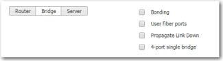
Access the Configuration - Deployment page. The three available bonding modes are:
|