This scenario deploys Site B in-line and the Site A network out-of-path with an available spare router port. It uses Policy-Based Routing (PBR) at the router to redirect traffic destined for the WAN to the Silver Peak appliance.
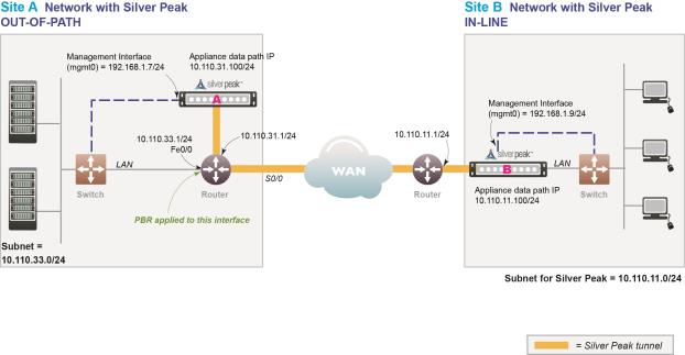 |
In this example, the Silver Peak appliance optimizes traffic to/from 10.110.33.0/24 and 10.110.11.0/24.
|
|||||
|
|||||
Fail-safe behavior should always be tested before production deployment by ensuring that traffic continues to flow in each of the following cases:
|
1
|
With the appliance in bypass state
|
|
2
|
With the appliance powered off
|
|
Gather all the IP addresses needed for setup
|
|||
|
Physical appliance: Connect the Site A appliance to the Site A router, and insert the Site B appliance between its WAN edge router and the Ethernet switch. Verify connectivity, connect power, and verify LEDs.
Virtual appliance: Configure the hypervisor, with the required interfaces.
|
|||
|
In a browser, access and use the Initial Configuration Wizard to configure each appliance — one in Bridge mode, the other in Router mode.
Reboot the appliance after finishing the configuration.
|
|||
|
Create a tunnel on each appliance
|
|||
|
Access the router’s command line interface, and configure the router for policy-based routing.
|
|||
|
n
|
Although it isn’t a requirement, it’s considered a best practice to use different subnets for mgmt0 and the Appliance data path IP.
|
|
mgmt0 IP Address / Mask1
|
||
|
LAN Next-hop IP Address (optional) 2
|
|
|
|
|