From each appliance, you must create a tunnel to each remote appliance to which it will be sending traffic.
We’ll create tunnels from Appliances A1 and A2 to B. Then we’ll create tunnels from B to A1 and to A2.
|
w
|
|
2
|
|
3
|
Click Add Tunnel.
|
 |
|
a
|
In the Name field, assign a locally significant name for the tunnel.
|
|
b
|
|
c
|
Leave Auto MTU selected. This allows the tunnel MTU to be discovered and negotiated automatically. When selected, this overrides the MTU setting.
|
|
d
|
In the Local IP field, the Appliance Manager prefills the IP address for the local appliance.
|
|
e
|
In the Remote IP address field, enter the data path IP address of the remote Silver Peak appliance.
|
|
f
|
Leave Auto Max BW selected, so the appliance uses the lower of the two system bandwidths.
|
If you wanted to configure this manually, then you would deselect Auto Max BW and, in the Max BW field, enter the maximum bandwidth for this tunnel. The value must be less than or equal to the upstream bandwidth of your WAN connection.
|
g
|
|
h
|
Click Apply.
|
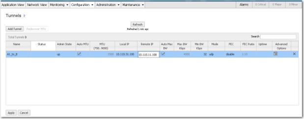
The tunnel status won’t change to Up until a tunnel is configured at both ends. That is, until after we configure a tunnel from B to A1.
|
w
|
|
2
|
|
3
|
Click Add Tunnel.
|
 |
|
a
|
In the Name field, assign a locally significant name for the tunnel.
|
|
b
|
|
c
|
Leave Auto MTU selected. This allows the tunnel MTU to be discovered and negotiated automatically. When selected, this overrides the MTU setting.
|
|
d
|
In the Local IP field, the Appliance Manager prefills the IP address for the local appliance.
|
|
e
|
In the Remote IP address field, enter the data path IP address of the remote Silver Peak appliance.
|
|
f
|
Leave Auto Max BW selected, so the appliance uses the lower of the two system bandwidths.
|
|
g
|
|
h
|
Click Apply.
|
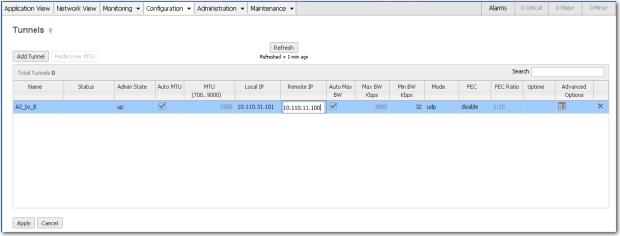
The tunnel status won’t change to Up until a tunnel is configured at both ends. So, we’ll now configure a tunnel from B to A1.
|
w
|
|
2
|
|
3
|
 |
|
a
|
In the Name field, assign a locally significant name for the tunnel.
|
|
b
|
|
c
|
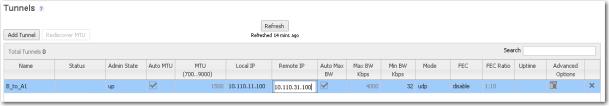
Click Apply.
|
|
4
|
 |
|
a
|
In the Name field, assign a locally significant name for the tunnel.
|
|
b
|
|
c
|
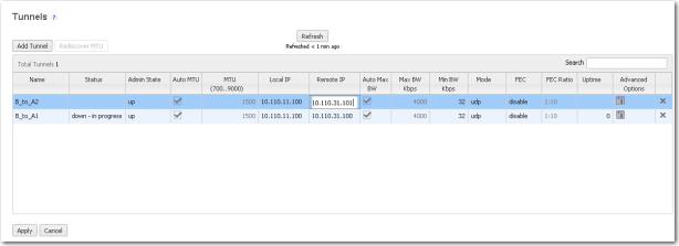
Click Apply.
|
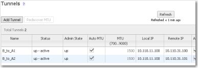
Within a few seconds, the Status of both tunnels should change to Up - active.
Click Refresh, if required.
Click Refresh, if required.
 |