Silver Peak SD-WAN Deployment Guide
In-Line deployments can be either Bridge modeIn-line deployment of an appliance, placing it between an Ethernet LAN switch and a WAN edge router. Use in 2 port or 4 port mode. or Router modeOut-of-path deployment, where data traffic is redirected by using policy-based routing (PBR), Web Cache Coordination Protocol (WCCP), or Virtual Router Redundancy Protocol (VRRP)..
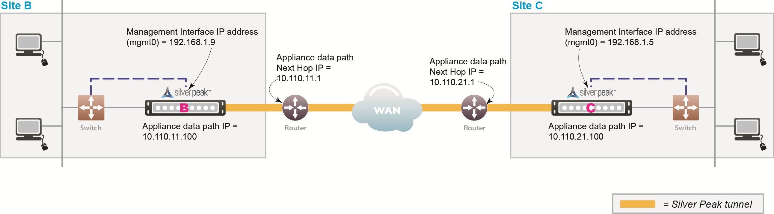
In an in-line deployment, the Silver Peak appliance is inserted in-line between the WANWide Area Network router and the Ethernet switchA network device that filters and forwards frames based on the destination address of each frame. The switch operates at Layer-2 (data link layer) of the Open System Interconnection (OSI) model. on the LANLocal Area Network. side of the network. In this mode, the appliance intercepts all packets destined for the WANWide Area Network. Based on the Route Policy’s MATCH criteria, or using SubnetA portion of a network that shares a common address component. On TCP/IP networks, subnets are defined as all devices whose IP addresses have the same prefix. For example, all devices with IP addresses that start with 100.100.100. would be part of the same subnet. Dividing a network into subnets is useful for both security and performance reasons. IP networks are divided using a subnet mask. Sharing-enabled auto-optimization, the appliance optimizes all flows that are directed to a tunnelEncapsulating one type of network protocol (called the payload protocol) within a different delivery protocol. A logical connection between two devices, in our case, two Silver Peak appliances.. If the BIO overlay Down action is pass-through, all other traffic passes through the appliance without optimization. Else, the default action is to drop.
In Bridge modeIn-line deployment of an appliance, placing it between an Ethernet LAN switch and a WAN edge router. Use in 2 port or 4 port mode., a failed appliance acts as a crossover cable. Best practice is to use a crossover cable between the appliance and the WANWide Area Network-side router, and a standard Ethernet cable between the appliance and the LANLocal Area Network.-side switchA network device that filters and forwards frames based on the destination address of each frame. The switch operates at Layer-2 (data link layer) of the Open System Interconnection (OSI) model.. Verify the physical layer connectivity between the L2 switchA network device that filters and forwards frames based on the destination address of each frame. The switch operates at Layer-2 (data link layer) of the Open System Interconnection (OSI) model. and router with the appliance turned off. If you don’t receive a link on the router or switchA network device that filters and forwards frames based on the destination address of each frame. The switch operates at Layer-2 (data link layer) of the Open System Interconnection (OSI) model., you need to correct the cabling.
Before deploying, gather information about your network, as shown in the following example:
Concepts
Tasks
Configuring Deployment Profiles
Related Topics
In-Line Bridge vs In-Line Router
In-Line Router Mode (Router + Firewall)
In-Line Router Mode (Router + Direct Internet)
In-Line Router Mode (Single Direct Internet)
In-Line Router Mode (Dual Direct Internet)
In-Line Router Mode (Dual MPLS)
Bridge Mode (Router + Direct Internet)
Bridge Mode (Router + Firewall)
Copyright © 2017 by Silver Peak Systems, Inc. All rights reserved. 